 English
 中文简体
 日本語
 русский
 عربى
 Український
 Español
 Français



How to Prepare a Factory for Potato Chips Line Installation
Content
- How to Prepare a Factory for Fabricated Potato Chips Production Line Installation
- 1. Why Factory Preparation Must Begin Before Equipment Delivery
- 2. Factory Layout, Equipment Positioning, and Access
- 3. Utilities and Infrastructure Readiness
- 4. Mechanical Installation and Process-Line Interfaces
- 5. The Factory Readiness Checklist
- 6. Common Installation Mistakes and How to Prevent Them
- 6.1 Mistake 1: Designing the factory around the machine footprint alone
- 6.2 Mistake 2: Preparing utilities from estimates rather than specifications
- 6.3 Mistake 3: Treating machine connections as interchangeable
- 6.4 Mistake 4: Ignoring the fryer environment during factory planning
- 6.5 Mistake 5: Completing mechanical installation without reviewing control integration
- 6.6 Mistake 6: Leaving cleaning arrangements until after installation
- 6.7 Mistake 7: Shipping equipment before the site has been verified
- 7. Supplier–Customer Responsibility Coordination
- 8. When Is a Factory Ready for Commissioning?
- Frequently Asked Questions
- 1. What information should be confirmed before a fabricated potato chips production line is shipped?
- 2. How can a factory verify electrical and utility requirements?
- 3. Why must installation clearances follow the approved layout?
- 4. Can commissioning begin before every utility and interface is ready?
- 5. What information should a customer request from the supplier?
- 6. Does every fabricated potato chips line require the same foundation, exhaust, and drainage arrangements?
- 7. How can a customer determine whether the factory is ready for installation?
- Conclusion: Factory Readiness Is Part of Process Engineering
How to Prepare a Factory for Fabricated Potato Chips Production Line Installation
Installing a fabricated potato chips production line is not simply a matter of delivering equipment, positioning machines, and connecting the power supply. It is an engineering project that requires coordination between factory infrastructure, process equipment, utility systems, mechanical interfaces, and operational safety.
A production line can be correctly manufactured and individually tested yet still experience installation delays if the factory floor is not ready, utility connections are incorrectly positioned, downstream equipment does not match the approved layout, or maintenance access has been overlooked.
For fabricated or stackable potato chips, these issues are particularly important because production involves several connected operations: dough preparation, sheeting, cutting, forming, frying, cooling, seasoning, and downstream handling. The exact configuration depends on the product, machine model, and agreed project scope.
Industrial processing suppliers such as Heat and Control illustrate how fabricated-chip processing integrates frying, oil filtration, oil heating, product cooling, seasoning, exhaust management, and controls.
Heat and Control
+1
This illustrates a central engineering principle: factory readiness must be evaluated for the complete production system, not just for individual machines.
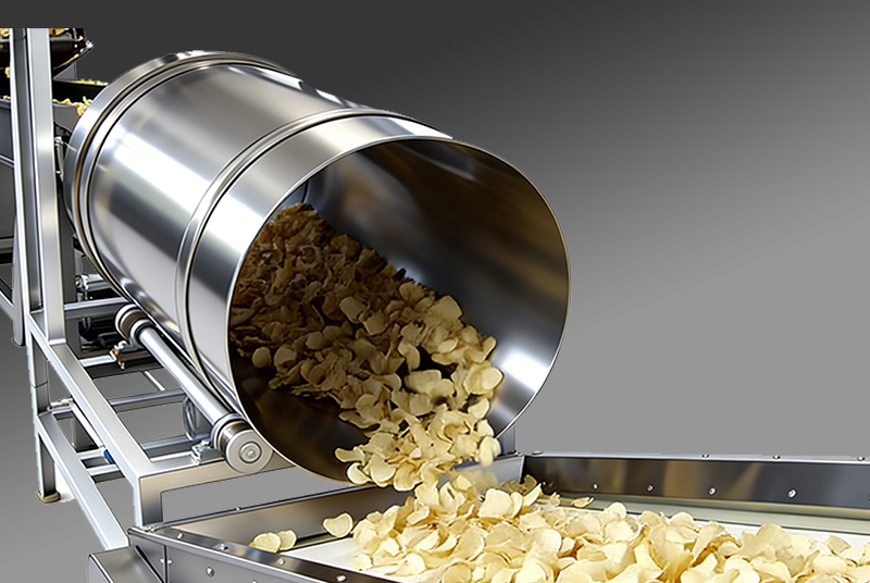
This guide explains how to prepare a factory before equipment delivery, how to verify installation readiness, and how the equipment supplier and customer can reduce avoidable project risks.
1. Why Factory Preparation Must Begin Before Equipment Delivery
Factory preparation should begin during project engineering, not after the equipment arrives.
Once a machine has been manufactured and shipped, changing its position, relocating a utility connection, modifying a platform, or altering a downstream conveyor may require additional work from the customer, local contractors, or the equipment supplier. These changes can also affect installation sequencing and commissioning.
The objective of Factory Readiness is to confirm that the site can physically receive the equipment, accommodate its operation and maintenance, provide the specified utilities, and support safe integration with the complete production process.
1.1 Factory readiness affects the entire project timeline
Consider the following sequence:
1. Project engineering
Confirm product requirements, machine configuration, layout and interfaces.
2. Factory preparation
Complete civil works, utilities, access routes, drainage and supporting infrastructure as applicable.
3. Equipment delivery and installation
Receive, position, align, connect and inspect the supplied equipment.
4. Commissioning and product trials
Verify safety, machine functions, process integration and product performance.
These stages are related but not interchangeable. A completed building does not necessarily mean the utilities are ready, and a mechanically installed line does not necessarily mean the process is ready for product trials.
1.2 The cost of discovering problems too late
Factory readiness issues typically fall into four categories.
-
Physical constraints: The equipment cannot enter the building, fit into its intended position, or be accessed for maintenance.
-
Utility deficiencies: Electrical capacity, heating infrastructure, compressed air, ventilation, or drainage does not meet the confirmed requirements.
-
Interface mismatches: Conveyor heights, transfer points, control signals, or downstream equipment do not match the approved configuration.
-
Operational constraints: Cleaning access, operator movement, material handling, or safety arrangements are inadequate.
Each issue may trigger additional contractor work, equipment repositioning, connection changes, retesting, or delays to commissioning.
The practical lesson is to identify these constraints while drawings can still be reviewed and modifications can be planned.
1.3 Establish a factory-readiness baseline
Before manufacturing is completed or equipment is dispatched, the supplier and customer should agree on a documented set of reference information:
-
Approved equipment layout and overall dimensions.
-
Equipment-specific installation and foundation requirements, if applicable.
-
Electrical, pneumatic, heating and other utility specifications.
-
Connection locations and interface drawings.
-
Equipment delivery and installation access arrangements.
-
Responsibility allocation for customer-supplied infrastructure.
-
Commissioning prerequisites and acceptance criteria.
Engineering rule: The approved project documents, rather than a generic installation checklist, must determine the actual technical requirements.
2. Factory Layout, Equipment Positioning, and Access
A factory can have sufficient total floor area and still be unsuitable for a production line. The critical question is whether the complete equipment configuration fits within the available space while preserving safe access, workable material flow, maintenance clearance, and all required utility connections.
2.1 Verify the equipment layout against actual site conditions
The approved layout should be checked against a current survey of the factory rather than relying exclusively on architectural drawings.
The survey should identify:
-
Building length, width, and usable internal height.
-
Columns, beams, doors, structural obstructions, and fixed services.
-
Floor levels, slopes, steps, trenches, and drains.
-
Locations of electrical distribution equipment and utility connection points.
-
Equipment foundations or supporting structures where required.
-
Available space for upstream preparation and downstream seasoning, conveying, and packaging equipment.
The review must consider the actual equipment footprint, including protruding motors, electrical cabinets, access doors, platforms, piping, and other supplied or customer-provided components.
A layout that accommodates the main machine bodies may still be unsuitable if a motor cannot be removed for servicing or a maintenance door cannot be fully opened.
2.2 Design for maintenance, not just installation
Maintenance clearance is the space needed to inspect, clean, adjust, or replace components during the equipment's service life.
For a fabricated potato chips line, this may include access to mixing equipment, sheeting and forming components, conveyors, fryer assemblies, oil-handling components, seasoning equipment, and electrical cabinets, depending on the configuration.
Why does this matter?
If a machine is positioned too close to a wall or another machine, maintenance personnel may be unable to reach a drive assembly, inspect a belt, remove a component, or safely isolate equipment for servicing. A small layout compromise during installation can therefore become a recurring operational problem.
The correct clearance is equipment-specific. It must be established from the supplier's installation and maintenance documentation, not from an assumed universal distance.
Verification method: Review the approved general arrangement drawing and confirm the relevant access areas physically at the site. Pay particular attention to removable parts, service doors, lifting arrangements, and the space required to withdraw components.
2.3 Confirm delivery and installation access
A machine's final position is only one part of the layout problem. It must also be possible to move the equipment into that position.
Before dispatch, verify:
-
The dimensions of building entrances and internal passageways.
-
Door opening height and width, including any obstructions.
-
Turning space for forklifts, pallet trucks, or other approved handling equipment.
-
Floor loading capacity and any restrictions on transport routes.
-
Crane or lifting access if the installation method requires it.
-
The dimensions and weights of the actual shipping packages or modules.
-
Temporary storage space for equipment awaiting installation.
The packaged dimensions may differ substantially from the operating footprint. A machine that fits inside the production hall may still be impossible to move through a doorway or around a column.
Lifting and handling arrangements must also account for the manufacturer's designated lifting points, package centre of gravity, load capacity of the handling equipment, and local workplace safety requirements.
Verification method: Compare shipping information and handling plans with measured site access dimensions. Confirm any special lifting requirements with the supplier before equipment delivery.
2.4 Coordinate material flow and downstream equipment
Fabricated potato chips production is a connected process. A typical line may include:
Dry ingredient preparation and mixing → water addition and wet mixing → sheeting → rotary cutting and forming → separation and appropriate trim handling → frying → cooling → seasoning → stacking and downstream handling.
The exact arrangement may vary. Some systems integrate particular operations, while others use separate modules or different product-handling arrangements.
The layout should therefore be checked in the direction of product movement.
For example, if the sheeting and forming section discharges at a height or position that does not match the frying section's infeed, the interface may require mechanical modification. If seasoning equipment is positioned too far from the cooling discharge, an additional conveyor or transfer arrangement may be needed.
These are not merely space-planning concerns. They affect product transfer, process continuity, access, and the integration of the line's controls.
The layout should also identify where raw materials enter, where finished product leaves, where operators work, and where waste or process residues are handled.
2.5 Confirm floor and structural requirements
Do not assume that every machine requires a special concrete foundation. Requirements depend on machine design, operating loads, support arrangements, and installation instructions.
The customer and local structural engineer should verify the floor's suitability for:
-
Static equipment loads.
-
Dynamic loads and vibration, where applicable.
-
Concentrated loads at support feet.
-
Additional loads from platforms, tanks, piping, or auxiliary equipment.
-
Any specified anchor bolts, embedded plates, or foundations.
Floor flatness, level, and elevation should be assessed against the supplier's actual installation requirements. An uneven floor can complicate positioning and alignment, while unsuitable support conditions may cause instability or difficulties connecting adjacent modules.
Factory-readiness decision: The layout is ready only when the supplied equipment can be delivered, installed, operated, cleaned, and maintained in the approved arrangement.
3. Utilities and Infrastructure Readiness
Utility planning is one of the most important parts of installation preparation because a machine cannot perform as intended if the supporting services are inadequate or incompatible.
However, fabricated potato chips production lines do not all have identical utility requirements. Heating method, motor configuration, control architecture, auxiliary equipment, and project scope can all affect the infrastructure needed.
The customer should obtain a project-specific utility schedule from HG's engineering team.
3.1 Electrical supply, grounding, and control interfaces
Electrical readiness involves more than confirming that a factory has a power connection.
The electrical review should cover:
-
Available supply voltage and frequency.
-
Electrical phase configuration.
-
Available capacity and expected loads.
-
Main isolation and protective devices.
-
Protective grounding and bonding.
-
Cable routing, cable entry locations, and distribution arrangements.
-
Control cabinet location and environmental conditions.
-
Interfaces with upstream and downstream equipment.
-
Requirements for external control signals, if applicable.
The supplier's electrical documentation should identify the equipment's required supply and connection arrangements. The customer's electrical contractor should then verify that the factory's distribution system can support those requirements.
For example, the total site load may include motors, mixing equipment, conveyors, heating systems, oil pumps, cooling equipment, seasoning systems, and auxiliary units. The actual load depends on which items are included in the supply scope and how they are powered.
Simply adding motor nameplate ratings may not be sufficient to establish the final site demand. The supplier's electrical design and the project's load assessment should be used to determine the appropriate capacity and protection.
Grounding is a safety requirement, not an optional commissioning adjustment. The electrical installation must be verified by qualified personnel against the equipment documentation and applicable local regulations.
Control interfaces require equal attention. A machine may have its own control panel, while communication with adjacent machines may require agreed signals or interlocks. The control interface should be documented before wiring begins.
Verification evidence: Approved electrical drawings, a utility schedule, confirmation of supply characteristics, and documented electrical inspection and test results.
3.2 Compressed air
Compressed air may be required for pneumatic actuators, cylinders, valves, or other equipment functions, depending on the supplied configuration.
The relevant questions are:
-
Which machines require compressed air?
-
What operating pressure range is specified?
-
What flow is required during normal and simultaneous operation?
-
What air-quality requirements apply?
-
Where should the connection be located?
-
Is isolation and pressure regulation required at the point of use?
A compressor's nominal capacity does not automatically establish that sufficient air will be available at the equipment connection. Pressure losses in pipework, other factory consumers, leaks, and simultaneous demand can affect actual performance.
Air quality also matters where moisture, oil, or particulate contamination could affect pneumatic components or the production environment.
Verification method: Compare the supplier's stated pressure, flow, and air-quality requirements with the compressor system and distribution design. Verify operating conditions at the relevant connection points.
Do not specify a universal pressure or flow value for every fabricated potato chips line.
3.3 Heating energy and frying-system requirements
The frying section requires particular attention because the heating arrangement influences the site's utility infrastructure.
Depending on the selected equipment, heating may use an electrical system or another specified energy source. Some industrial frying systems use external heating arrangements, heat exchangers, oil circulation, filtration, and related support equipment. Heat and Control's published fabricated-chip system information illustrates these possible process interfaces, but its particular design should not be assumed to apply to a HG installation.
Before construction or equipment delivery, confirm:
-
The specified heating method.
-
The required energy source and available capacity.
-
Any burner, fuel supply, or associated safety requirements, if applicable.
-
Oil circulation, filtration, transfer, and storage interfaces included in the project.
-
Required isolation, monitoring, and protective arrangements.
-
The interface between the fryer and any exhaust or heat-removal system.
-
Local approvals applicable to the selected heating and fuel arrangement.
Fuel type, operating pressure, energy consumption, and exhaust requirements must come from the actual project specification. They should not be inferred from another manufacturer's equipment or a different model.
Where oil storage, transfer, filtration, or cooling is included, these systems must also be considered in the factory layout and utility plan.
Verification method: Conduct a joint review of the fryer documentation, utility schedule, site energy supply, and applicable local requirements before equipment shipment.
3.4 Exhaust, ventilation, and heat removal
Frying and other heat-generating operations can produce heat, moisture, oil mist, and odours. The quantity and characteristics depend on the process, equipment enclosure, heating arrangement, product, and operating conditions.
The factory should determine whether the project requires dedicated exhaust, general ventilation, local extraction, heat removal, or pollution-control equipment.
The review should consider:
-
Exhaust connection locations and dimensions.
-
The specified extraction capacity and operating conditions.
-
Make-up air requirements.
-
Discharge location and applicable environmental restrictions.
-
Access for inspection and cleaning.
-
Potential effects on indoor temperature and surrounding work areas.
A common design error is to provide an exhaust duct without verifying the required airflow or the interaction between extraction and make-up air. An inadequately designed system may fail to control heat or airborne contaminants as intended. Excessive or poorly balanced extraction may also interfere with the local airflow or create unwanted pressure differences.
Verification method: Have the supplier and qualified local ventilation engineer agree on the required interface and system design. Confirm applicable environmental, fire-safety, and occupational requirements before installation.
3.5 Drainage, cleaning, and hygiene provisions
Cleaning requirements should be considered during layout development rather than after the machinery is installed.
The required arrangement depends on the equipment's cleaning method and the customer's food-safety procedures. Some components may require dry cleaning, controlled wet cleaning, or specific cleaning-in-place arrangements. These methods should not be assumed to be interchangeable.
The factory review should identify:
-
Approved cleaning methods for each relevant machine.
-
Water and cleaning-service requirements, where applicable.
-
Drainage points and their relationship to equipment.
-
The need to contain oil, residues, or cleaning effluent.
-
Protection of electrical equipment and sensitive components.
-
Access for cleaning, inspection, and maintenance.
-
The approved handling and disposal of process waste.
A drain located under a machine support or in an inaccessible position may be difficult to clean. Poor drainage planning can also lead to standing water, contamination risks, or interference with maintenance activities.
The customer should not assume that the entire line is designed for washdown or that every component is suitable for direct water cleaning.
Verification method: Confirm cleaning instructions with the supplier and have the plant's hygiene or food-safety representative approve the proposed cleaning and drainage arrangement.
3.6 Build a project-specific utility schedule
The utility schedule should identify the service required, its specification, the connection point, the responsible party, and the evidence needed to verify readiness.
|
Utility or service |
Information to confirm |
Verification |
|---|---|---|
|
Electrical supply |
Voltage, frequency, phases, load, protection and connection location |
Approved electrical drawings and qualified inspection |
|
Protective grounding |
Required grounding and bonding arrangements |
Electrical test and inspection records |
|
Compressed air |
Pressure, flow, quality and connection point, if required |
Supplier specification and site measurements |
|
Heating energy |
Heating method, energy source, capacity and safety provisions |
Equipment specification and local engineering review |
|
Exhaust and ventilation |
Required extraction, make-up air and discharge arrangements |
Approved ventilation design and functional checks |
|
Water and drainage |
Applicable cleaning requirements, drainage and waste handling |
Approved hygiene plan and site inspection |
|
Control interfaces |
Signals, interlocks, isolation and integration requirements |
Interface drawings and agreed test plan |
The values in this schedule must be populated from the actual HG equipment configuration and project documents. They are not universal specifications for fabricated potato chips production lines.
4. Mechanical Installation and Process-Line Interfaces
Mechanical installation is the stage at which the approved design becomes a physical production system. The objective is not simply to position every machine, but to ensure that the machines, supporting structures, conveyors, utility connections, and control interfaces work together as intended.
4.1 Positioning, leveling, and alignment
Before positioning equipment, the installation team should identify the agreed reference points and confirm the floor conditions.
The team should then follow the manufacturer's instructions for placement, support, leveling, anchoring, and alignment, as applicable.
These activities matter because equipment modules may need to connect to adjacent conveyors, transfer points, piping, or other machinery. If the installed position differs from the approved layout, connections may not line up correctly.
Potential consequences include:
-
Difficulty connecting adjacent modules.
-
Unintended loads on connecting structures or piping.
-
Belt tracking or transfer problems.
-
Increased vibration or mechanical wear where alignment is affected.
-
Rework before the line can be tested.
Alignment tolerances and leveling requirements must be obtained from the applicable installation drawings and manuals. Do not apply an assumed tolerance to every machine.
Verification method: Record the actual equipment position, check alignment against the approved reference points, and document any deviations before proceeding with dependent connections.
4.2 Conveyor height and transfer-point coordination
Conveyors are often treated as relatively simple components, but they are critical process interfaces.
In a fabricated potato chips line, the product passes through multiple operations in a defined sequence. The transfer between forming, frying, cooling, seasoning, and downstream handling must be compatible with the equipment's design.
The installation review should establish:
-
Infeed and discharge elevations.
-
Conveyor width and direction of travel.
-
Transfer-point geometry.
-
Product-handling requirements at each interface.
-
Drive and speed-control arrangements.
-
Access for cleaning and maintenance.
-
Any required communication between the adjoining machines.
The consequences of a poorly matched interface depend on the product and equipment. They may include product accumulation, interrupted transfer, damage to formed pieces, uneven loading, or excessive manual handling.
The correct interface cannot be determined from a general arrangement drawing alone if the relevant connection details are missing.
Verification method: Review interface drawings before delivery, then inspect the physical transfer points during installation. Confirm that the actual connection matches the approved design.
4.3 Mechanical interfaces between modules
Not every connection between machines is a simple conveyor connection.
Depending on the project, interfaces may involve support frames, oil-handling pipework, exhaust ducts, electrical conduits, pneumatic lines, guards, or access platforms.
The project team should clarify which components are supplied by HG and which must be supplied or installed by the customer or local contractor.
For example, a machine may include an internal oil circulation assembly while external service connections are within the customer's scope. If the boundary is not defined, each party may assume that the other will complete the work.
A mechanical interface register can help prevent this problem.
|
Interface |
Questions to resolve |
|---|---|
|
Machine-to-machine |
Who supplies the connecting conveyor, frame, or transfer assembly? |
|
Equipment-to-building |
Are supports, anchors, or structural modifications required? |
|
Fryer-to-utility system |
Who supplies external piping, isolation, and service connections? |
|
Equipment-to-exhaust |
What connection is included, and who completes the ductwork? |
|
Equipment-to-control system |
Who supplies the cables, signals, and integration work? |
|
Equipment-to-packaging |
Are the discharge height, throughput, and operating modes compatible? |
Each interface should have a named owner and a drawing or written specification.
4.4 Electrical controls, interlocks, and emergency stops
A line containing multiple machines needs a coordinated safety and control approach.
An interlock is a control arrangement that prevents or restricts an operation unless a defined condition is satisfied. Depending on the machine design, this may involve guards, access doors, operating sequences, or communication between equipment modules.
Emergency-stop functions must also be considered as part of the complete installation. The required locations, coverage, reset behaviour, and relationship between connected machines depend on the equipment risk assessment, control design, and applicable regulations.
Simply connecting several machines to power does not establish that their control systems operate safely as an integrated line.
The project team should confirm:
-
Which control functions are local to each machine.
-
Which signals must be exchanged between machines.
-
How start-up and shutdown sequences are coordinated.
-
How abnormal conditions affect upstream and downstream equipment.
-
Which emergency-stop and protective functions apply.
-
How safety functions will be tested and documented.
Verification method: Use the approved electrical schematics, control-interface documentation, and safety assessment to prepare a functional test plan. Qualified personnel should test the required protective functions before normal production operation.
4.5 Why individual machine operation is not enough
A machine can operate correctly on its own while the complete production line still fails to perform as required.
Consider a hypothetical interface problem: the forming section runs at a stable speed, and the fryer conveyor operates correctly during an independent test. If their actual transfer rates or interface positions are incompatible, continuous production may still be interrupted.
This is a general engineering example, not a documented HG customer case.
The same principle applies to cooling, seasoning, stacking, and downstream packaging. Each unit may pass its own functional test while the overall system experiences accumulation, starvation, inconsistent transfer, or repeated stops.
Process Integration therefore requires verification at two levels:
-
Individual-machine verification: Each supplied machine operates according to its applicable requirements.
-
Integrated-line verification: Connected machines exchange product and control signals correctly and operate together under the agreed test conditions.
A successful installation must address both.
5. The Factory Readiness Checklist
The following checklist can be used during project preparation and the pre-installation review. It is a general engineering framework; the final checklist should be adapted to the actual equipment scope.
|
Inspection item |
Why it matters |
Evidence or verification method |
Responsible party to confirm |
|---|---|---|---|
|
Approved equipment layout |
Establishes machine positions and interfaces |
Signed-off layout drawing |
Supplier + customer project engineer |
|
Actual building dimensions |
Identifies conflicts with columns, doors and structures |
Site survey compared with drawings |
Customer + local contractor |
|
Delivery access |
Prevents equipment from becoming trapped during unloading or movement |
Measured access routes and handling plan |
Customer + installation team |
|
Floor and support conditions |
Ensures suitable support and positioning |
Site inspection and structural assessment, where required |
Customer + structural engineer |
|
Maintenance clearances |
Allows servicing, inspection and cleaning |
Layout review against service documentation |
Supplier + customer maintenance team |
|
Electrical supply |
Ensures compatibility with equipment requirements |
Electrical drawings and site verification |
Supplier + customer electrician |
|
Grounding and protection |
Supports electrical safety |
Qualified inspection and test records |
Customer electrician + responsible safety personnel |
|
Compressed air |
Prevents pneumatic functions from being impaired, if required |
Pressure, flow and quality verification |
Supplier + customer utilities team |
|
Heating and fuel systems |
Ensures compatibility with the selected process configuration |
Approved utility schedule and safety review |
Supplier + customer utilities contractor |
|
Exhaust and ventilation |
Addresses heat, oil mist, odours and applicable environmental requirements |
Approved design and functional verification |
Customer + ventilation contractor + supplier |
|
Drainage and cleaning |
Supports hygiene and maintenance requirements |
Cleaning plan and site inspection |
Customer hygiene team + supplier |
|
Conveyor and transfer interfaces |
Maintains product flow between modules |
Interface drawings and dimensional inspection |
Supplier + installation team |
|
Electrical and control interfaces |
Enables coordinated operation |
Schematics, signal list and interface test plan |
Supplier + customer automation team |
|
Guards and emergency stops |
Supports safe installation and operation |
Risk assessment and documented functional tests |
Supplier + customer safety personnel |
|
Downstream connections |
Avoids incompatibility with seasoning, handling or packaging |
Agreed interface specifications |
Customer + supplier + downstream equipment provider |
|
Installation tools and lifting equipment |
Enables safe and efficient equipment handling |
Approved lifting and installation plan |
Customer + installation contractor |
|
Commissioning materials |
Allows planned tests to be carried out |
Agreed trial-material and test plan |
Supplier + customer production team |
|
Readiness approval |
Prevents installation from proceeding with unresolved critical issues |
Signed factory-readiness review |
Customer project manager + supplier representative |
How to use the checklist
Do not treat every item as a simple yes-or-no question. A utility may exist but still be unsuitable, and a layout drawing may exist without having been checked against the current site.
For each item, record one of the following:
-
Ready: Evidence has been reviewed and the requirement is satisfied.
-
Open: Work remains, or the evidence is incomplete.
-
Not applicable: The requirement does not apply to the agreed equipment configuration.
-
Hold point: An unresolved issue must be addressed before the relevant installation or commissioning activity proceeds.
A readiness review should identify the person responsible, the corrective action, and the evidence required to close each open item.
A signed checklist is useful only when it reflects verified site conditions.

6. Common Installation Mistakes and How to Prevent Them
The following risks are general industrial equipment installation risks. They are not claims about documented HG customer failures.
6.1 Mistake 1: Designing the factory around the machine footprint alone
What goes wrong: The machine fits into the building, but operators cannot access important components, maintenance doors cannot open fully, or lifting equipment cannot reach parts that need servicing.
Why it happens: Layout planning focuses on the main machine dimensions rather than the complete installation and operating envelope.
Potential consequence: Repositioning, additional structural work, difficult maintenance, or avoidable downtime.
Preventive action: Review the general arrangement drawing together with service clearances, access doors, lifting requirements, and the actual site survey before finalizing the layout.
6.2 Mistake 2: Preparing utilities from estimates rather than specifications
What goes wrong: Electrical capacity, compressed air, heating services, or exhaust connections are unsuitable for the supplied equipment.
Why it happens: The customer relies on previous factory equipment, a similar machine, or assumptions about typical utility consumption.
Potential consequence: Additional electrical work, utility-system modifications, delayed testing, or equipment operation outside its specified conditions.
Preventive action: Request the project-specific utility schedule and connection drawings. Have the responsible local contractor verify the site against those documents.
6.3 Mistake 3: Treating machine connections as interchangeable
What goes wrong: Conveyor transfer points, piping connections, support structures, or downstream interfaces do not match.
Why it happens: The project team assumes that similar-looking machines have identical interfaces or uses preliminary drawings after the design has changed.
Potential consequence: Fabrication rework, additional adapters, alignment difficulties, or interrupted product flow.
Preventive action: Use the latest approved drawings and maintain an interface register. Review all changes with the supplier before installation.
6.4 Mistake 4: Ignoring the fryer environment during factory planning
What goes wrong: The building's exhaust, heat-removal, oil-handling, or cleaning arrangements do not match the actual frying system.
Why it happens: The fryer is treated as an isolated machine rather than a process module with supporting services.
Potential consequence: Unsuitable working conditions, cleaning difficulties, unresolved environmental requirements, or delays to commissioning.
Preventive action: Confirm the fryer configuration and its associated utility, ventilation, oil-handling, and cleaning interfaces with the supplier and qualified local engineers.
The specific requirements depend on the selected design; they should not be copied from another frying system.
6.5 Mistake 5: Completing mechanical installation without reviewing control integration
What goes wrong: Individual machines run, but the integrated line has incompatible operating sequences, missing signals, or unresolved interlocks.
Why it happens: Mechanical completion is treated as proof that the entire line is ready.
Potential consequence: Repeated stops, unreliable product transfer, unsafe operating conditions, or additional commissioning work.
Preventive action: Agree on the control architecture, signal list, start-up and shutdown logic, and functional test plan before wiring and integration are completed.
6.6 Mistake 6: Leaving cleaning arrangements until after installation
What goes wrong: Drains, access points, cleaning connections, or waste-handling arrangements are difficult to use once the equipment is in position.
Why it happens: Cleaning is considered an operational issue rather than a factory-layout requirement.
Potential consequence: Poor accessibility, increased cleaning effort, water-management problems, or hygiene risks.
Preventive action: Review the approved cleaning method for each relevant component before finalizing the layout. Confirm drainage and cleaning interfaces with the plant's hygiene team.
6.7 Mistake 7: Shipping equipment before the site has been verified
What goes wrong: Equipment arrives while the factory floor, utilities, access routes, or supporting structures are still incomplete.
Why it happens: The shipment date becomes the main project milestone, while readiness is judged by construction progress rather than evidence.
Potential consequence: Extended storage, repeated handling, installation disruption, and additional project costs.
Preventive action: Hold a formal pre-dispatch readiness review. Record unresolved issues, responsible parties, closure dates, and any agreed restrictions before the shipment decision.
The most effective preventive measure across all seven scenarios is early coordination backed by approved documents and verified site conditions.
7. Supplier–Customer Responsibility Coordination
Many installation problems are not caused by a machine defect or a building defect. They arise because the boundary between the equipment supplier's work and the customer's work has not been clearly defined.
A successful project needs an agreed division of responsibilities before equipment delivery.
7.1 Define who supplies, installs, and verifies each interface
A project-specific responsibility matrix should distinguish four activities:
-
Supply: Who provides the component or service?
-
Installation: Who physically installs and connects it?
-
Verification: Who checks that it meets the agreed requirements?
-
Approval: Who formally accepts the result?
These activities may belong to different parties.
For example, the equipment supplier may provide electrical drawings, the customer may arrange the site electrical installation, a qualified electrician may perform the required tests, and the customer's project manager may approve the completed work.
Providing a drawing does not automatically mean that the supplier is responsible for installing the corresponding site infrastructure.
7.2 Recommended responsibility matrix
The following is an illustrative allocation. The final arrangement must be agreed in the project contract and technical scope.
|
Activity |
Equipment supplier |
Customer |
Local contractor / specialist |
|---|---|---|---|
|
Equipment layout and supplied-machine dimensions |
Prepare and confirm supplied equipment information |
Review and approve site arrangement |
Support site survey where required |
|
Site readiness and building conditions |
Provide equipment-specific requirements |
Coordinate and confirm site readiness |
Inspect or complete assigned civil works |
|
Equipment utility specifications |
Provide applicable technical requirements |
Review and coordinate site services |
Design or install assigned utility systems |
|
Delivery and unloading |
Provide equipment weights, dimensions and handling instructions |
Arrange site access and coordinate delivery |
Provide agreed lifting and handling services |
|
Mechanical installation |
Install or supervise as contractually agreed |
Provide site coordination and support |
Complete assigned installation work |
|
Electrical and control integration |
Provide equipment schematics and defined interface information |
Coordinate the overall project |
Install and test assigned site wiring and services |
|
Safety and guarding |
Provide equipment-specific documentation and supplied protective components |
Coordinate site safety and operating procedures |
Complete assigned site safety work |
|
Commissioning |
Perform or support agreed machine and process tests |
Provide utilities, personnel and agreed trial materials |
Support required site testing |
|
Final acceptance |
Demonstrate agreed equipment functions |
Review results and formally accept according to the contract |
Provide records for work within its scope |
A clear matrix reduces uncertainty about external piping, ductwork, cable routing, foundations, connecting conveyors, and other interfaces that may not be included in the equipment supply.
7.3 Conduct a formal pre-installation review
Before equipment arrives, arrange a joint review involving the supplier's project or engineering representative, the customer's project manager, and the relevant local contractors.
The review should confirm:
-
The current approved equipment configuration and layout.
-
The completion status of civil works and equipment access.
-
The readiness of electrical and other required utilities.
-
The status of mechanical and downstream interfaces.
-
The agreed responsibilities for unresolved items.
-
The planned installation and commissioning sequence.
-
The documents and tests required for acceptance.
Every unresolved issue should have a named owner and a defined closure condition.
The meeting should produce a written record, not just a verbal agreement.
8. When Is a Factory Ready for Commissioning?
A factory is not ready for commissioning simply because all machines have arrived or have been positioned on the floor.
Commissioning should begin only when the prerequisites for the planned test stage have been satisfied.
The required prerequisites depend on the equipment configuration, the type of test, the applicable safety requirements, and the agreed project scope.
8.1 Understand the four stages
Stage 1 — Installation completion
Equipment has been positioned, assembled, connected and inspected according to the applicable installation requirements. Outstanding defects and incomplete work are recorded.
Stage 2 — Dry-run testing
Relevant machines and mechanisms are tested without product, using the approved test procedure. The team verifies functions, movement, controls, protective devices and applicable interlocks.
Stage 3 — Integrated-line testing
Connected equipment is tested together to verify transfer interfaces, operating sequences, control communication and coordinated responses to defined operating conditions.
Stage 4 — Product trial production
The line processes the agreed materials under defined conditions. The team evaluates product quality, process stability and the contractual performance criteria applicable to the trial.
These stages may overlap or be organized differently in a particular contract, but the distinction between mechanical completion, functional testing, integrated operation, and product trials should remain clear.
8.2 Verify the prerequisites for each stage
Before dry-run testing
Confirm that the relevant installation work is complete, required utilities are available, electrical and mechanical checks have been carried out, and the equipment can be tested safely.
Before integrated-line testing
Confirm that individual machines have passed the applicable tests, interfaces have been checked, control signals are correctly connected, and the agreed interlocks and emergency-stop functions have been verified.
Before product trials
Confirm that the equipment is safe to operate with product, the relevant cleaning and hygiene requirements have been satisfied, utilities are stable, and the agreed raw materials and trial procedures are available.
For fabricated potato chips, product trials may require coordination of the dough-preparation, sheeting, forming, frying, cooling, and seasoning operations, according to the supplied configuration. Product acceptance should be based on agreed trial conditions and measurable criteria rather than a general statement that the machine is running.
8.3 Can commissioning begin if a utility or interface is not ready?
It depends on the missing requirement and the proposed test.
A machine-specific inspection or a limited test may be possible while unrelated work remains incomplete. However, the team must not bypass required safety measures or conduct a test that depends on an unavailable or unverified service.
For example, an integrated-line test cannot meaningfully verify the intended operating sequence if a necessary downstream connection or control interface is missing. A heating or frying test must not proceed without the applicable heating-system safety conditions and required services.
The commissioning plan should identify hold points and state which activities are permitted, which are restricted, and which cannot proceed until the relevant issue is resolved.
8.4 Installation acceptance versus production acceptance
Installation acceptance and production acceptance are different decisions.
Installation acceptance generally concerns whether the equipment has been installed and completed according to the agreed scope and applicable requirements.
Production acceptance concerns whether the system meets the agreed functional and process-performance criteria under the specified test conditions.
Depending on the contract, these criteria may address output, product characteristics, operating stability, or other defined requirements. The exact criteria, measurement methods, and permitted test conditions must be agreed in advance.
A documented commissioning report should record test results, outstanding issues, corrective actions, and the parties responsible for sign-off.
Frequently Asked Questions
1. What information should be confirmed before a fabricated potato chips production line is shipped?
Confirm the approved equipment configuration, layout, shipping dimensions and weights, utility schedule, installation requirements, mechanical and electrical interfaces, delivery access, and responsibility matrix. The customer and supplier should also agree on the commissioning prerequisites and the handling of any outstanding site issues.
2. How can a factory verify electrical and utility requirements?
Request the project-specific utility schedule and relevant electrical, mechanical, and interface drawings from the equipment supplier. Have qualified local specialists compare these documents with the actual site infrastructure and verify the required supply characteristics and connection conditions.
Do not rely on generic industry values or specifications from another machine model.
3. Why must installation clearances follow the approved layout?
Clearances provide the space required for installation, operation, cleaning, inspection, maintenance, and component removal. A machine may physically fit into a building while still being inaccessible for servicing. The approved layout should therefore account for the complete operating and maintenance envelope, not just the machine footprint.
4. Can commissioning begin before every utility and interface is ready?
Some limited inspections or machine-specific tests may be possible if they are covered by the approved test plan and can be performed safely. Tests that depend on missing utilities, incomplete connections, or unverified safety functions must wait until their prerequisites are satisfied.
5. What information should a customer request from the supplier?
At a minimum, request the approved layout, equipment dimensions and weights, installation instructions, utility schedule, electrical drawings, interface specifications, maintenance requirements, applicable safety documentation, and commissioning plan. Additional documents depend on the equipment configuration and project scope.
6. Does every fabricated potato chips line require the same foundation, exhaust, and drainage arrangements?
No. These requirements depend on the machine design, heating configuration, cleaning method, structural loads, site conditions, and local regulations. The supplier should provide equipment-specific requirements, while qualified local engineers determine and verify the appropriate building and utility provisions.
7. How can a customer determine whether the factory is ready for installation?
Conduct a documented factory-readiness review against the approved project documents. Verify the site dimensions, equipment access, floor and support conditions, required utilities, mechanical interfaces, safety provisions, and cleaning arrangements. Assign an owner and closure requirement to every unresolved item before authorizing the relevant installation activity.
Conclusion: Factory Readiness Is Part of Process Engineering
Preparing a factory for a fabricated potato chips production line is an essential part of the engineering process. It connects equipment design with building infrastructure, utility systems, mechanical installation, controls, safety, and production requirements.
The most effective approach is to identify and verify interfaces before equipment delivery. An approved layout, a project-specific utility schedule, clearly allocated responsibilities, and a documented readiness review give the supplier and customer a common basis for installation and commissioning.
The ultimate objective is not merely to install every machine. It is to establish the conditions needed for the complete production line to operate safely, integrate reliably, and meet its agreed production requirements.
HG helps food manufacturers plan fabricated potato chips production solutions around their equipment configuration and project requirements. Discuss your proposed production capacity, factory layout, and installation conditions with our team before equipment delivery so that the relevant interfaces can be reviewed and confirmed.
Website: https://www.hg-machine.com/

A historic signing moment from the 1970s, when HG’s founder helped drive the development of China’s food industry and began expanding into international markets.
Over the past decades, we have participated in the evolution of automated food production — from local factories to global turnkey projects across 100+ countries. That experience continues to shape every HG production line today.
Discover Our Heritage
Global Food Machinery &
Turnkey Factory Solutions

Building Long-Term Partnerships Through Shared Growth and Industrial Value.
Copyright © HG Industry Group All Rights Reserved
Food Machine Snack Food Processing Machinery

Unauthorized use of this website's content constitutes copyright infringement and may result in legal action.